IRI Configuration Examples
This section contains a number of code snippets demonstrating how to configure the Indy for various purposes. The code snippets are not complete programs, in contrast with the IRI Example Programs. The code snippets should be added into existing C programs to include their function.
The Indy Modules are configured primarily by setting key code values using the ipj_set, ipj_set_value, or ipj_bulk_set functions. The Indy Module applies the configuration settings when the ipj_start function is called.
See the Configuration Commands section for more details on these functions.
See the Key Codes section for a complete list of keys.
Key values may be read from the Indy Module by using the ipj_get, ipj_get_value, or ipj_bulk_get functions. This can be useful for determining the present configuration, or for reading certain parameters of performance or operation, like the current temperature of the module.
Warning
Key values will persist until they are changed or the device is reset. It is important to explictly configure keys for each operation in a manner which are deterministic. For example, if a Tag operation is enabled the device will perform the configured tag operation on each start command until disabled. Key values can be configured across resets using the Stored Settings functionality.
Configuration Commands
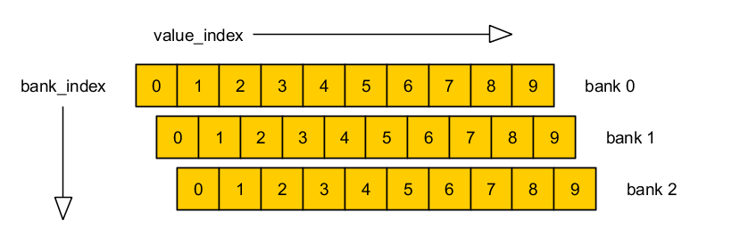
ipj_set/ipj_get and ipj_bulk_set/ipj_bulk_get require the inclusion of bank_index and value_index parameters. These parameters correspond to the position of the value in the key that the user is trying to modify.
The majority of keys are a single value/bank which require a bank_index and value_index of 0. In these cases, we recommend the user use the convenience functions ipj_set_value and ipj_get_value (which masks this detail).
There are also three types of ‘complex’ keys:
- Key lists - These are individual keys which can contain a list of data. An example of this would be channel tables. In these cases, the user would supply a value_index corresponding to the particular item in the list they would like to access. (These are indexed starting at 0).
- Banked Keys - These are keys which exist in several ‘banks’ or instances. An example of this would be the SELECT_XXX keys. To access the settings for a select command instance, you would provide its bank number. (These are indexed starting at 0).
- Banked Key lists - These are keys which contain lists of values, and which also exist as several ‘banks’ or instances. An example of this would be the E_IPJ_KEY_SELECT_MASK_VALUE Key. The value_index would correspond to the mask values for the select command instance, and the bank_index corresponds to the particular select command instance.
The following diagram details this layout:
Bulk Set vs Set Usage
The ipj_bulk_set is the most efficient way to set multiple key values at once using the API.
Note
The Stored Settings functionality can be used to store key values in non-volatile memory in the Indy Module, removing the need to re-configure the module the same way each time after reset.
// Example usage of bulk_set in the ITK
ipj_key_value   key_value[16];
uint32_t        key_value_count;
ipj_key_list    key_list;
uint32_t        key_list_count;

memset(key_value, 0, sizeof(key_value));
key_value_count = 2;
key_value[0].key = E_IPJ_KEY_ANTENNA_TX_POWER;
key_value[0].value = 2000;
key_value[1].key = E_IPJ_KEY_INVENTORY_TAG_POPULATION;
key_value[1].value = 5;

memset(&key_list, 0, sizeof(key_list));
key_list_count = 1;
key_list.key = E_IPJ_KEY_ANTENNA_SEQUENCE;
key_list.list_count = 16;
key_list.list[0] = 1;
key_list.list[1] = 2;
key_list.list[2] = 3;
key_list.list[3] = 4;
// All other list items initialized to 0 by memset

ipj_bulk_set(&iri_device, &key_value[0], key_value_count, &key_list, key_list_count);
However, ipj_bulk_set is not available in ITK-LT and an example of how to convert a bulk_set to a group of sets is illustrated below.
// Example equivalence of bulk_set in the ITK-LT, due to lack of bulk_set in ITK-LT
ipj_set_value(&iri_device, E_IPJ_KEY_ANTENNA_TX_POWER, 2000);
ipj_set(&iri_device, E_IPJ_KEY_INVENTORY_TAG_POPULATION, 0, 0, 5); // Alternate to ipj_set_value
ipj_set(&iri_device, E_IPJ_KEY_ANTENNA_SEQUENCE, 0, 0, 1);
ipj_set(&iri_device, E_IPJ_KEY_ANTENNA_SEQUENCE, 0, 1, 2);
ipj_set(&iri_device, E_IPJ_KEY_ANTENNA_SEQUENCE, 0, 2, 3);
ipj_set(&iri_device, E_IPJ_KEY_ANTENNA_SEQUENCE, 0, 3, 4);
ipj_set(&iri_device, E_IPJ_KEY_ANTENNA_SEQUENCE, 0, 4, 0);
ipj_set(&iri_device, E_IPJ_KEY_ANTENNA_SEQUENCE, 0, 5, 0);
ipj_set(&iri_device, E_IPJ_KEY_ANTENNA_SEQUENCE, 0, 6, 0);
ipj_set(&iri_device, E_IPJ_KEY_ANTENNA_SEQUENCE, 0, 7, 0);
ipj_set(&iri_device, E_IPJ_KEY_ANTENNA_SEQUENCE, 0, 8, 0);
ipj_set(&iri_device, E_IPJ_KEY_ANTENNA_SEQUENCE, 0, 9, 0);
ipj_set(&iri_device, E_IPJ_KEY_ANTENNA_SEQUENCE, 0, 10, 0);
ipj_set(&iri_device, E_IPJ_KEY_ANTENNA_SEQUENCE, 0, 11, 0);
ipj_set(&iri_device, E_IPJ_KEY_ANTENNA_SEQUENCE, 0, 12, 0);
ipj_set(&iri_device, E_IPJ_KEY_ANTENNA_SEQUENCE, 0, 13, 0);
ipj_set(&iri_device, E_IPJ_KEY_ANTENNA_SEQUENCE, 0, 14, 0);
ipj_set(&iri_device, E_IPJ_KEY_ANTENNA_SEQUENCE, 0, 15, 0);

// NOTE: It will not be necessary in all cases to send all values in bank.
// For example, after reset all values will be 0 for E_IPJ_KEY_ANTENNA_SEQUENCE
// (see Defaults for other keys).  So the host code can be optimized when
// writing IRI-LT host code.
Reading Data From Reports
When the Indy reader modules are configured to communicate information about RFID operations, they communicate that information via reports. There are reports for tag operations, RFID status, stopped actions, and errors. The reports are structs that have members representing a variety of information. Many of these members will not be populated unless they are enabled using the report control keys, for example E_IPJ_KEY_REPORT_CONTROL_TAG and E_IPJ_KEY_REPORT_CONTROL_STATUS.
These reports are handled by API functions in the ipj_util.c source file, as described in the Report Handler Interface section of the Platform and Report Handlers documentation. The report handler functions are called in the generic ipj_util_report_handler(...) function in ipj_util.c, with the reports themselves as arguments. Within each of the individual report handlers, the data fields in the report representing data about RFID operations can be accessed as members of the report structs.
For specific examples on how to read data from these reports, continue reading the examples below.
Reading EPCs
To access the EPC of a tag after it is read by an inventory, simply examine the tag.epc.bytes member of the tag_operation_report, as shown in the following code snippet. The IRI_Intro example program also demonstrates reading tag EPCs and printing them to the console.
The following code is an example implementation of the ipj_util_tag_operation_report_handler() function in ipj_util.c:
/* Tag report handler processes asynchronous reports */
ipj_error ipj_util_tag_operation_report_handler(
        ipj_iri_device* iri_device,
        ipj_tag_operation_report* tag_operation_report)
{
    /* If tag report has epc, print epc */
    if (tag_operation_report->tag.has_epc)
    {
        ipj_util_print_epc(
                (uint16_t*) tag_operation_report->tag.epc.bytes,
                (int) tag_operation_report->tag.epc.size / 2,
                true);
    }

    return E_IPJ_ERROR_SUCCESS;
}
Measuring RSSI
RSSI, or received signal strength indicator, is measured every time a tag responds to inventory. This measurement indicates the strength of the signal that is received from the tag, and can provide information about the forward and reverse links between the reader and the tag. For more information on RSSI, see the Frequently Asked Questions.
To read the RSSI measurements, they must first be enabled by setting the E_IPJ_TAG_FLAG_BIT_RSSI flag in the key E_IPJ_KEY_REPORT_CONTROL_TAG, as shown in the first code snippet below.
When enabled, the measurement is included as the rssi member of the tag struct, which is a member of each ipj_tag_operation_report, which can be read in the ipj_util_tag_operation_report_handler() function in the ipj_util.c source file, as shown in the second code snippet below.
To enable RSSI measurement communication, place the following code snippet in your main() function before the inventory is started:
ipj_set_value(&iri_device, E_IPJ_KEY_REPORT_CONTROL_TAG, E_IPJ_TAG_FLAG_BIT_RSSI);
And to print out the RSSI measurements, modify the ipj_util_tag_operation_report_handler(...) function in ipj_util.c as shown below:
/* Tag report handler processes asynchronous reports */
ipj_error ipj_util_tag_operation_report_handler(
        ipj_iri_device* iri_device,
        ipj_tag_operation_report* tag_operation_report)
{
    /* If tag report has RSSI, print RSSI */
    if (tag_operation_report->tag.has_rssi)
    {
        printf(" rssi = %d cdBm", tag_operation_report->tag.rssi);
    }

    return E_IPJ_ERROR_SUCCESS;
}
Note
The units of RSSI are centi-dB-mW (cdBm), and the value is signed.
Measuring Reverse Power
Reverse Power is a measurement of how much power is refected from the antenna port back towards the Indy Module. This measurement can indicate when an antenna is improperly matched, or removed entirely, or if there is some other obstruction in the signal path. Indy Modules measure both forward and reverse power every time the radio is turned on, which happens every time a new inventory is initiated, and also every time the radio hops from channel to channel. For more information on reverse power, see the frequently asked questions.
These measurements will be included in the status_report struct if the channel activity flag E_IPJ_STATUS_FLAG_BIT_CHANNEL_ACTIVITY is set in key E_IPJ_KEY_REPORT_CONTROL_STATUS, as shown in the first code snippet below.
The reverse power measurement can then be read by examining the status_report data[1] member in the ipj_util_status_report_handler(...) function in the ipj_util.c source file, as shown in the second code snippet below.
To enable reverse power measurement communication, place the following code snippet in your main() function before the inventory is started:
ipj_set_value(&iri_device, E_IPJ_KEY_REPORT_CONTROL_STATUS, E_IPJ_STATUS_FLAG_BIT_CHANNEL_ACTIVITY);
And to print out the reverse power measurements, modify the ipj_util_status_report_handler(...) function in ipj_util.c as shown below:
/* Status report handler processes asynchronous reports */
ipj_error ipj_util_status_report_handler(
        ipj_iri_device* iri_device,
        ipj_status_report* status_report)
{
    printf(" reverse power = %d cdBm", status_report->data[1]);

    return E_IPJ_ERROR_SUCCESS;
}
Note
The units of reverse power are centi-dB-mW (cdBm), and the value is signed.
Measuring Power Amplifier (PA) temperature (RS1000 only)
PA Die Temperature is the temperature of the power amplifer die measured in Celcius [C]. The PA Die Temperature can be read by examining the status_report data[2] member.
CPU Internal Temperature is the measured CPU internal temperature Celcius [C]. The CPU Internal Temperature can be read by examining the status_report data[3] member.
PA Die Over Temperature Flag indicates that the PA die temperature has exceeded 130 C. The PA Die Over Temperature Flag is a boolean value held in the status_report data[4] member.
On RS1000 when the PA Die Temperature exceeds 150 C then RF activity is stopped and a stopped actions report is sent with the error enumeration value E_IPJ_ERROR_LIMIT_PA_TEMPERATURE_MAX set as the error_code data member.
- On RS1000 when the PA Die Temperature exceeds 130 C:
- The RF duty cycle will be reduced in order to avoid the 150 C thermal upper limit. This will result in significantly reduced tag access rates.
- The PA Die Over Temperature Flag will be set to ‘1’.
Radio Control
Regulatory Region
This configuration example shows how to configure an Indy Module for a specific regulatory region.
For information on how to configure an Indy Module for a custom (non-standard) regulatory region, see the configuration example Custom Regulatory Region.
The Indy Modules support a broad range of regulatory regions. The regulatory regions are listed in the regions section of this documentation.
Configure the regulatory region using the E_IPJ_KEY_REGION_ID key.
Note
Each Indy Module SKU has different regional support. See the Indy Module datasheets for more details on which regions are supported by which SKU.
The following code snippet sets the regulatory region to ETSI EN 302 208 v1.4.1:
ipj_set_value(&iri_device, E_IPJ_KEY_REGION_ID, E_IPJ_REGION_ETSI_EN_302_208_V1_4_1);
Transmit Power
Configure the transmit power using the E_IPJ_KEY_ANTENNA_TX_POWER key.
The following code snippet sets the transmit power to 20.00 dBm:
ipj_set_value(&iri_device, E_IPJ_KEY_ANTENNA_TX_POWER, 2000);
RF Mode
Configure the RF Mode using the E_IPJ_KEY_RF_MODE key.
The following code snippet sets the RF Mode to 3:
ipj_set_value(&iri_device, E_IPJ_KEY_RF_MODE, 3);
Antenna Switching
Configure the antenna switching sequence using the E_IPJ_KEY_ANTENNA_SEQUENCE key.
For generic antenna numbering, see ipj_antenna.
For details on RS2000 antenna numbering, see ipj_antenna_rs2000.
The following code snippet sets the antenna switching sequence to 1, 2, 4, 3, 2:
ipj_key_list    key_list;
uint32_t        key_list_count;

memset(&key_list, 0, sizeof(key_list));

key_list_count = 1;
key_list.key = E_IPJ_KEY_ANTENNA_SEQUENCE;

key_list.list_count = 16;
key_list.list[0] = 1;
key_list.list[1] = 2;
key_list.list[2] = 4;
key_list.list[3] = 3;
key_list.list[4] = 2;
// All other list items initialized to 0 by memset

ipj_bulk_set(&iri_device, 0, 0, &key_list, key_list_count);
RFID Configuration
Indy Modules manage Tag populations using three basic operations:
- Select: Select operations may be applied to select a particular Tag population based on user-specified critieria.
- Inventory: The Indy Module identifies individual Tags during Inventory. Tag EPCs are reported in Tag Operation Reports.
- Access: The Indy Module communicates with individual Tags using Access operations. Access operations include the following: reading tag memory, writing tag memory, locking tag memory, blockpermalocking tag memory, and killing a tag. Results of Access operations are reported in Tag Operation Reports.
Details of the Select, Inventory, and Access operations may be found in the UHF Gen2 specification: GS1/EPCglobal Radio-Frequency Identity Protocol Generation-2 UHF RFID Protocol for Communications at 860 MHz - 960 MHz. Version 1.20
Users configure the Select, Inventory, and Access parameters prior to calling the ipj_start function. In response to the ipj_start function, the Indy Module will transmit the appropriate Select, Inventory, and Access commands. Results of Inventory and Access operations are reported in Tag Operation Reports.
Select Parameters
The Select operation is optional.
Configure Select operation using the following keys (see the EPC UHF Gen2 Air Interface Protocol specification for details about the Select command):
- E_IPJ_KEY_SELECT_ENABLE
- E_IPJ_KEY_SELECT_TARGET
- E_IPJ_KEY_SELECT_ACTION
- E_IPJ_KEY_SELECT_MEM_BANK
- E_IPJ_KEY_SELECT_POINTER
- E_IPJ_KEY_SELECT_MASK_LENGTH
- E_IPJ_KEY_SELECT_MASK_VALUE
Warning
Setting E_IPJ_KEY_SELECT_ENABLE to TRUE will persist until changed, causing all inventories to use the select configuration. If no longer desired, the user must configure the key value back to FALSE.
Example Select operation configuration
ipj_set_value(&iri_device, E_IPJ_KEY_SELECT_ENABLE, true);
ipj_set_value(&iri_device, E_IPJ_KEY_SELECT_TARGET, E_IPJ_SELECT_TARGET_SL_FLAG);
ipj_set_value(&iri_device, E_IPJ_KEY_SELECT_ACTION, E_IPJ_SELECT_ACTION_ASLINVA_DSLINVB);
ipj_set_value(&iri_device, E_IPJ_KEY_SELECT_MEM_BANK, E_IPJ_MEM_BANK_EPC);
ipj_set_value(&iri_device, E_IPJ_KEY_SELECT_POINTER, 0x20);
ipj_set_value(&iri_device, E_IPJ_KEY_SELECT_MASK_LENGTH, 96);
ipj_set(&iri_device, E_IPJ_KEY_SELECT_MASK_VALUE, 0, 0, 0x0123);
ipj_set(&iri_device, E_IPJ_KEY_SELECT_MASK_VALUE, 0, 1, 0x4567);
ipj_set(&iri_device, E_IPJ_KEY_SELECT_MASK_VALUE, 0, 2, 0x89AB);
ipj_set(&iri_device, E_IPJ_KEY_SELECT_MASK_VALUE, 0, 3, 0xCDEF);
ipj_set(&iri_device, E_IPJ_KEY_SELECT_MASK_VALUE, 0, 4, 0xFFFF);
ipj_set(&iri_device, E_IPJ_KEY_SELECT_MASK_VALUE, 0, 5, 0x0001);
Enabling the Select operation results in the Indy Module sending a Select command before each Inventory round.
It is also necessary to configure Inventory to identify and report selected tags using at minimum the E_IPJ_KEY_INVENTORY_SELECT_FLAG key (based on the use case and select target selected in the Select Command):
ipj_set_value(&iri_device, E_IPJ_KEY_INVENTORY_SELECT_FLAG, E_IPJ_INVENTORY_SELECT_FLAG_SL);
After the Indy Module is configured:
- Start inventory using ipj_start
- Process Tag Operation Reports in report handler
- Set the E_IPJ_KEY_SELECT_ENABLE value to FALSE to return to default behavior
Inventory Parameters
Configuration of the Inventory parameters is not required in all applications. The Indy Module defaults to a standard Inventory configuration. It is recommended that users configure the Inventory parameters for specific applications as needed.
The following keys control the Inventory operation (see the EPC UHF Gen2 Air Interface Protocol specification for details):
- E_IPJ_KEY_INVENTORY_TAG_POPULATION
- E_IPJ_KEY_INVENTORY_SELECT_FLAG
- E_IPJ_KEY_INVENTORY_SESSION
- E_IPJ_KEY_INVENTORY_SEARCH_MODE
Example Inventory parameter configuration
ipj_set_value(&iri_device, E_IPJ_KEY_INVENTORY_TAG_POPULATION, 10);
ipj_set_value(&iri_device, E_IPJ_KEY_INVENTORY_SELECT_FLAG, E_IPJ_INVENTORY_SELECT_FLAG_ALL_SL);
ipj_set_value(&iri_device, E_IPJ_KEY_INVENTORY_SESSION, 2);
ipj_set_value(&iri_device, E_IPJ_KEY_INVENTORY_SEARCH_MODE, E_IPJ_INVENTORY_SEARCH_MODE_DUAL_TARGET);
The following keys enable Impinj Inventory extensions:
ipj_set_value(&iri_device, E_IPJ_KEY_FAST_ID_ENABLE, true);
ipj_set_value(&iri_device, E_IPJ_KEY_TAG_FOCUS_ENABLE, true);
After the Indy Module is configured:
- Start inventory using ipj_start
- Process Tag Operation Reports in report handler
- Set the E_IPJ_KEY_SELECT_ENABLE value to FALSE to return to default behavior
Access Parameters
Access operations enable users to read Tag memory, write Tag memory, lock Tag memory and kill a Tag.
Users configure the Indy Module for the desired read, write, lock, blockpermalock, or kill operation. The Indy Module will perform the desired Access operation on each Tag that is inventoried. The results are provided in the Tag Operation Reports.
Read
The following keys enable Read operation (see the EPC UHF Gen2 Air Interface Protocol specification for details about the Read command):
- E_IPJ_KEY_TAG_OPERATION_ENABLE
- E_IPJ_KEY_TAG_OPERATION
- E_IPJ_KEY_ACCESS_PASSWORD (optional, for secure access)
- E_IPJ_KEY_READ_MEM_BANK
- E_IPJ_KEY_READ_WORD_POINTER
- E_IPJ_KEY_READ_WORD_COUNT
Warning
Setting E_IPJ_KEY_TAG_OPERATION_ENABLE to TRUE will persist until changed, causing all inventories to perform the configured tag operation. If no longer desired, the user must configure the key value back to FALSE.
Example Read configuration:
ipj_set_value(&iri_device, E_IPJ_KEY_TAG_OPERATION_ENABLE, true);
ipj_set_value(&iri_device, E_IPJ_KEY_TAG_OPERATION, E_IPJ_TAG_OPERATION_TYPE_READ);
ipj_set_value(&iri_device, E_IPJ_KEY_READ_MEM_BANK, E_IPJ_MEM_BANK_TID);
ipj_set_value(&iri_device, E_IPJ_KEY_READ_WORD_POINTER, 0x00);
ipj_set_value(&iri_device, E_IPJ_KEY_READ_WORD_COUNT, 2);
After the Indy Module is configured:
- Start inventory using ipj_start
- Process Tag Operation Reports to view read data
- Set the E_IPJ_KEY_SELECT_ENABLE value to FALSE to return to default behavior
Write
The following keys enable writing tag memory using the Write and BlockWrite commands:
- E_IPJ_KEY_TAG_OPERATION_ENABLE
- E_IPJ_KEY_TAG_OPERATION
- E_IPJ_KEY_ACCESS_PASSWORD (optional, for secure access)
- E_IPJ_KEY_WRITE_MEM_BANK
- E_IPJ_KEY_WRITE_WORD_POINTER
- E_IPJ_KEY_WRITE_WORD_COUNT
- E_IPJ_KEY_WRITE_DATA
- E_IPJ_KEY_BLOCK_WRITE_OVERRIDE
Warning
Setting E_IPJ_KEY_TAG_OPERATION_ENABLE to TRUE will persist until changed, causing all inventories to perform the configured tag operation. If no longer desired, the user must configure the key value back to FALSE.
Example Write configuration, writing 7 words of tag EPC Memory:
ipj_set_value(&iri_device, E_IPJ_KEY_TAG_OPERATION_ENABLE, true);
ipj_set_value(&iri_device, E_IPJ_KEY_TAG_OPERATION, E_IPJ_TAG_OPERATION_TYPE_WRITE);
ipj_set_value(&iri_device, E_IPJ_KEY_WRITE_MEM_BANK, E_IPJ_MEM_BANK_EPC);
ipj_set_value(&iri_device, E_IPJ_KEY_WRITE_WORD_POINTER, 0x01);
ipj_set_value(&iri_device, E_IPJ_KEY_WRITE_WORD_COUNT, 7);
ipj_set(&iri_device, E_IPJ_KEY_WRITE_DATA, 0, 0, 0x3000);
ipj_set(&iri_device, E_IPJ_KEY_WRITE_DATA, 0, 1, 0xAAAA);
ipj_set(&iri_device, E_IPJ_KEY_WRITE_DATA, 0, 2, 0x5555);
ipj_set(&iri_device, E_IPJ_KEY_WRITE_DATA, 0, 3, 0x0123);
ipj_set(&iri_device, E_IPJ_KEY_WRITE_DATA, 0, 4, 0x4567);
ipj_set(&iri_device, E_IPJ_KEY_WRITE_DATA, 0, 5, 0x89AB);
ipj_set(&iri_device, E_IPJ_KEY_WRITE_DATA, 0, 6, 0xCDEF);
Note
Memory writes will be performed using either a Write or BlockWrite command, depending on the configuration.
If the key E_IPJ_KEY_WRITE_WORD_COUNT is set to a value of 1, a Write will be performed.
If the word count is greater than 1, a BlockWrite will be performed if an Impinj Monza tag is being used, or a series of single word Writes if a non-Monza tag is used.
This configuration can be overwritten using the key E_IPJ_KEY_BLOCK_WRITE_OVERRIDE
Alternatively, ipj_bulk_set can be used to configure the Indy Module to write tag memory with a single function call
ipj_key_value   key_value[16];
uint32_t        key_value_count;
ipj_key_list    key_list;
uint32_t        key_list_count;

memset(key_value, 0, sizeof(key_value));
memset(&key_list, 0, sizeof(key_list));

key_value_count = 5;

key_value[0].key = E_IPJ_KEY_TAG_OPERATION_ENABLE;
key_value[0].value = true;

key_value[1].key = E_IPJ_KEY_TAG_OPERATION;
key_value[1].value = E_IPJ_TAG_OPERATION_TYPE_WRITE;

key_value[2].key = E_IPJ_KEY_WRITE_MEM_BANK;
key_value[2].value = E_IPJ_MEM_BANK_EPC;

key_value[3].key = E_IPJ_KEY_WRITE_WORD_POINTER;
key_value[3].value = 1;

key_value[4].key = E_IPJ_KEY_WRITE_WORD_COUNT;
key_value[4].value = 7;

key_list_count = 1;
key_list.key = E_IPJ_KEY_WRITE_DATA;

key_list.list_count = 7;
key_list.list[0] = 0x3000;
key_list.list[1] = 0xAAAA;
key_list.list[2] = 0x5555;
key_list.list[3] = 0x0123;
key_list.list[4] = 0x4567;
key_list.list[5] = 0x89AB;
key_list.list[6] = 0xCDEF;

ipj_bulk_set(&iri_device, &key_value[0], key_value_count, &key_list, key_list_count);
After the Indy Module is configured:
- Start inventory using ipj_start
- Process Tag Operation Reports to confirm successful writes
- Set the E_IPJ_KEY_SELECT_ENABLE value to FALSE to return to default behavior
Write EPC
The Write EPC operation writes Tag EPC memory and optionally updates the PC word. When the Write EPC operation is selected, the Indy Module automatically selects the EPC memory bank and EPC word pointer. Additionally, the Indy Module updates the PC word according to the ...EPC_LENGTH_CONTROL and ...AFI_CONTROL key values. The following keys enable Write EPC operation (see the EPC UHF Gen2 Air Interface Protocol specification for details):
- E_IPJ_KEY_TAG_OPERATION_ENABLE
- E_IPJ_KEY_TAG_OPERATION
- E_IPJ_KEY_ACCESS_PASSWORD (optional, for secure access)
- E_IPJ_KEY_WRITE_EPC_LENGTH_CONTROL
- E_IPJ_KEY_WRITE_EPC_LENGTH_VALUE
- E_IPJ_KEY_WRITE_EPC_AFI_CONTROL
- E_IPJ_KEY_WRITE_EPC_AFI_VALUE
- E_IPJ_KEY_WRITE_WORD_COUNT
- E_IPJ_KEY_WRITE_DATA
Warning
Setting E_IPJ_KEY_TAG_OPERATION_ENABLE to TRUE will persist until changed, causing all inventories to perform the configured tag operation. If no longer desired, the user must configure the key value back to FALSE.
Example Write EPC configuration:
ipj_set_value(&iri_device, E_IPJ_KEY_TAG_OPERATION_ENABLE, true);
ipj_set_value(&iri_device, E_IPJ_KEY_TAG_OPERATION, E_IPJ_TAG_OPERATION_TYPE_WRITE_EPC);
ipj_set_value(&iri_device, E_IPJ_KEY_WRITE_EPC_LENGTH_CONTROL, E_IPJ_WRITE_EPC_LENGTH_CONTROL_AUTO);
ipj_set_value(&iri_device, E_IPJ_KEY_WRITE_EPC_AFI_CONTROL, 0);
ipj_set_value(&iri_device, E_IPJ_KEY_WRITE_EPC_AFI_VALUE, 0);
ipj_set_value(&iri_device, E_IPJ_KEY_WRITE_WORD_COUNT, 6);
ipj_set(&iri_device, E_IPJ_KEY_WRITE_DATA, 0, 0, 0xAAAA);
ipj_set(&iri_device, E_IPJ_KEY_WRITE_DATA, 0, 1, 0x5555);
ipj_set(&iri_device, E_IPJ_KEY_WRITE_DATA, 0, 2, 0x0123);
ipj_set(&iri_device, E_IPJ_KEY_WRITE_DATA, 0, 3, 0x4567);
ipj_set(&iri_device, E_IPJ_KEY_WRITE_DATA, 0, 4, 0x89AB);
ipj_set(&iri_device, E_IPJ_KEY_WRITE_DATA, 0, 5, 0xCDEF);
After the Indy Module is configured:
- Start inventory using ipj_start
- Process Tag Operation Reports to confirm successful writes
- Set the E_IPJ_KEY_SELECT_ENABLE value to FALSE to return to default behavior
Lock
The following keys enable the Lock operation (see the EPC UHF Gen2 Air Interface Protocol specification for details about the Lock command):
- E_IPJ_KEY_TAG_OPERATION_ENABLE
- E_IPJ_KEY_TAG_OPERATION
- E_IPJ_KEY_ACCESS_PASSWORD (optional, for secure access)
- E_IPJ_KEY_LOCK_PAYLOAD
Warning
Setting E_IPJ_KEY_TAG_OPERATION_ENABLE to TRUE will persist until changed, causing all inventories to perform the configured tag operation. If no longer desired, the user must configure the key value back to FALSE.
Example Lock configuration:
ipj_set_value(&iri_device, E_IPJ_KEY_TAG_OPERATION_ENABLE, true);
ipj_set_value(&iri_device, E_IPJ_KEY_TAG_OPERATION, E_IPJ_TAG_OPERATION_TYPE_LOCK);
ipj_set_value(&iri_device, E_IPJ_KEY_LOCK_PAYLOAD, 0xFFFFF);
After the Indy Module is configured:
- Start inventory using ipj_start
- Process Tag Operation Reports to confirm successful lock
BlockPermalock
The following keys enable the BlockPermalock operation (see the EPC UHF Gen2 Air Interface Protocol specification for details about the BlockPermalock command):
- E_IPJ_KEY_TAG_OPERATION_ENABLE
- E_IPJ_KEY_TAG_OPERATION
- E_IPJ_KEY_ACCESS_PASSWORD (optional, for secure access)
- E_IPJ_KEY_BLOCKPERMALOCK_ACTION
- E_IPJ_KEY_BLOCKPERMALOCK_MEM_BANK
- E_IPJ_KEY_BLOCKPERMALOCK_BLOCK_POINTER
- E_IPJ_KEY_BLOCKPERMALOCK_BLOCK_RANGE
- E_IPJ_KEY_BLOCKPERMALOCK_MASK
Warning
Setting E_IPJ_KEY_TAG_OPERATION_ENABLE to TRUE will persist until changed, causing all inventories to perform the configured tag operation. If no longer desired, the user must configure the key value back to FALSE.
Example Blockpermalock configuration:
ipj_set_value(&iri_device, E_IPJ_KEY_TAG_OPERATION_ENABLE, true);
ipj_set_value(&iri_device, E_IPJ_KEY_TAG_OPERATION, E_IPJ_TAG_OPERATION_TYPE_BLOCKPERMALOCK);
ipj_set_value(&iri_device, E_IPJ_KEY_BLOCKPERMALOCK_ACTION, E_IPJ_BLOCKPERMALOCK_ACTION_PERMALOCK);
ipj_set_value(&iri_device, E_IPJ_KEY_BLOCKPERMALOCK_MEM_BANK, E_IPJ_MEM_BANK_USER);
ipj_set_value(&iri_device, E_IPJ_KEY_BLOCKPERMALOCK_BLOCK_POINTER, 0x00);
ipj_set_value(&iri_device, E_IPJ_KEY_BLOCKPERMALOCK_BLOCK_RANGE, 1);
ipj_set_value(&iri_device, E_IPJ_KEY_BLOCKPERMALOCK_MASK, 0x1);
After the Indy Module is configured:
- Start inventory using ipj_start
- Process Tag Operation Reports to confirm successful blockpermalock
- Set the E_IPJ_KEY_SELECT_ENABLE value to FALSE to return to default behavior
Kill
The following keys enable the Kill operation (see the EPC UHF Gen2 Air Interface Protocol specification for details about the Kill procedure):
Warning
Setting E_IPJ_KEY_TAG_OPERATION_ENABLE to TRUE will persist until changed, causing all inventories to perform the configured tag operation. If no longer desired, the user must configure the key value back to FALSE.
Example Kill configuration:
ipj_set_value(&iri_device, E_IPJ_KEY_TAG_OPERATION_ENABLE, true);
ipj_set_value(&iri_device, E_IPJ_KEY_TAG_OPERATION, E_IPJ_TAG_OPERATION_TYPE_KILL);
ipj_set_value(&iri_device, E_IPJ_KEY_KILL_PASSWORD, 0x01234567);
After the Indy Module is configured:
- Start inventory using ipj_start
- Process Tag Operation Reports to confirm success
QT Configuration
The following keys enable the QT operation:
- E_IPJ_KEY_TAG_OPERATION_ENABLE
- E_IPJ_KEY_TAG_OPERATION
- E_IPJ_KEY_ACCESS_PASSWORD (optional, for secure access)
- E_IPJ_KEY_QT_ACTION
- E_IPJ_KEY_QT_PERSISTENCE
- E_IPJ_KEY_QT_DATA_PROFILE
- E_IPJ_KEY_QT_ACCESS_RANGE
- E_IPJ_KEY_QT_TAG_OPERATION
Warning
Setting E_IPJ_KEY_TAG_OPERATION_ENABLE to TRUE will persist until changed, causing all inventories to perform the configured tag operation. If no longer desired, the user must configure the key value back to FALSE.
Example QT configuration:
ipj_set_value(&iri_device, E_IPJ_KEY_TAG_OPERATION_ENABLE, true);
ipj_set_value(&iri_device, E_IPJ_KEY_TAG_OPERATION, E_IPJ_TAG_OPERATION_TYPE_QT);
ipj_set_value(&iri_device, E_IPJ_KEY_QT_ACTION, E_IPJ_QT_ACTION_READ);
After the Indy Module is configured:
- Start inventory using ipj_start
- Process Tag Operation Reports in report handler to confirm success
Example QT configuration to read public EPC:
ipj_set_value(&iri_device, E_IPJ_KEY_TAG_OPERATION_ENABLE, true);
ipj_set_value(&iri_device, E_IPJ_KEY_TAG_OPERATION, E_IPJ_TAG_OPERATION_TYPE_QT);
ipj_set_value(&iri_device, E_IPJ_KEY_QT_ACTION, E_IPJ_QT_ACTION_WRITE);
ipj_set_value(&iri_device, E_IPJ_KEY_QT_PERSISTENCE, E_IPJ_QT_PERSISTENCE_TEMPORARY);
ipj_set_value(&iri_device, E_IPJ_KEY_QT_DATA_PROFILE, E_IPJ_QT_DATA_PROFILE_PUBLIC);
ipj_set_value(&iri_device, E_IPJ_KEY_QT_ACCESS_RANGE, E_IPJ_QT_ACCESS_RANGE_NORMAL);
ipj_set_value(&iri_device, E_IPJ_KEY_QT_TAG_OPERATION, E_IPJ_TAG_OPERATION_TYPE_READ);
ipj_set_value(&iri_device, E_IPJ_KEY_READ_MEM_BANK, E_IPJ_MEM_BANK_EPC);
ipj_set_value(&iri_device, E_IPJ_KEY_READ_WORD_POINTER, 2);
ipj_set_value(&iri_device, E_IPJ_KEY_READ_WORD_COUNT, 6);
After the Indy Module is configured:
- Start inventory using ipj_start
- Process Tag Operation Reports to confirm success
- Set the E_IPJ_KEY_SELECT_ENABLE value to FALSE to return to default behavior
Retry Mechanism
The Access Retry feature is enabled using the E_IPJ_KEY_TAG_OPERATION_RETRIES key. The Access operation is retried up to maximum number of retries specified by the key. A retry is not attempted if the Tag returns a Memory Overrun or Memory Locked error condition. The number of attempted retries is reported in the Tag Operation Report
GPIO Configuration
The Indy Module possesses 4 user controllable GPIO pins which can be configured as general purpose outputs, inputs, or action-attached inputs. Outputs can be driven either high or low. Inputs exist in either a high-impedance, pulled up, or pulled down state.
Note
The Default state for all GPIO pins is high-impedance input AKA “High-Z”.
The following keys enable the GPIO operation:
- E_IPJ_KEY_GPIO_MODE
- E_IPJ_KEY_GPIO_STATE
- E_IPJ_KEY_GPIO_HI_ACTION
- E_IPJ_KEY_GPIO_LO_ACTION
- E_IPJ_KEY_GPIO_DEBOUNCE_MS
Note
GPIO_PULSE is not yet supported
Each key is banked and therefore requires the use of an index value corresponding to the appropriate GPIO (1-4). Index 0 Is reserved for future functionality.
Once all appropriate keys are set, the GPIO configuration is initialized by sending the Indy Module a ipj_start command with the action argument E_IPJ_ACTION_GPIO.
GPIO Output
To configure GPIO 1 as an output and set it’s state to logic high (+3v3):
ipj_set(&iri_device, E_IPJ_KEY_GPIO_MODE, 1, 0, E_IPJ_GPIO_MODE_OUTPUT);
ipj_set(&iri_device, E_IPJ_KEY_GPIO_STATE, 1, 0, E_IPJ_GPIO_STATE_HI);
ipj_start(&iri_device, E_IPJ_ACTION_GPIO);
ipj_stop(&iri_device, E_IPJ_ACTION_GPIO);
GPIO Input
To configure GPIO 1 as an input with an internal pull-down (0v):
ipj_set(&iri_device, E_IPJ_KEY_GPIO_MODE, 1, 0, E_IPJ_GPIO_MODE_INPUT);
ipj_set(&iri_device, E_IPJ_KEY_GPIO_STATE, 1, 0, E_IPJ_GPIO_STATE_HI);
ipj_start(&iri_device, E_IPJ_ACTION_GPIO);
/* At this point, the user should call ipj_receive and handle any
 * incoming GPIO reports.  When the desired amount of reports have
 * been collected, the user should call ipj_stop and poll for the gpio
 * stop report */
ipj_stop(&iri_device, E_IPJ_ACTION_GPIO);
GPIO Input w/ Action
To configure GPIO 1 as a floating input that will start inventory when it is pulled high (+3v3):
ipj_set(&iri_device, E_IPJ_KEY_GPIO_MODE, 1, 0, E_IPJ_GPIO_MODE_INPUT_ACTION);
ipj_set(&iri_device, E_IPJ_KEY_GPIO_STATE, 1, 0, E_IPJ_GPIO_STATE_FLOAT);
ipj_set(&iri_device, E_IPJ_KEY_GPIO_HI_ACTION, 1, 0, E_IPJ_GPI_ACTION_START_INVENTORY);
ipj_start(&iri_device, E_IPJ_ACTION_GPIO);
/* At this point, the user should begin calling ipj_receive().  When
 * there is a logic-high event on the selected pin, the user will
 * receive a GPIO report, followed by tag reports as tags come into
 * the field.  When the user has received the desired number of tag
 * reports, they should:
 * 1. issue an ipj_stop(&iri_device, E_IPJ_ACTION_INVENTORY) command
 * 2. call ipj_receive until they receive an inventory stop report.
 * 3. issue an ipj_stop(&iri_device, E_IPJ_ACTION_GPIO) command
 * 4. call ipj_receive until they receive a gpio stop report
 */
ipj_stop(&iri_device, E_IPJ_ACTION_GPIO);
It is currently only possible to start and stop inventory via an input pin. Please see ipj_gpi_action for more info
GPIO Input Debounce
The GPIO input logic allows for a user programmable debounce period to be set in increments of 1 ms, set using the key E_IPJ_KEY_GPIO_DEBOUNCE_MS. If the debounce period is set to 0 (default), any input events will be reported and (if appropriately configured) acted upon. If it is set to > 0, the firmware will suppress any events that fall short of fulfilling his lockout period.
Furthermore, the internal GPI control is handled via polling, and the debounce timer has a tickrate of 100 us. As a result, the best-case response time will be debounce_time +/-100 us. The user should therefore not set the debounce time too close to the total expected period of the input trigger signal.
GPIO Input Debounce Example
Debounce period is set to 9 ms. The target GPI is held high for exactly 9 ms. Due to the resolution of the debounce timer, the debounce clock expires at 9.09 ms, and the event is missed.
For the Above scenario to function as intended, either the debounce rate would need to be reduced to 8 ms, or the GPI hold time would need to be extended.
Setting the debounce key:
/* Set the Debounce rate for GPIO 1 to 8ms */
ipj_set(&iri_device, E_IPJ_KEY_GPIO_DEBOUNCE_MS, 1, 0, 8);
Custom Configuration
Report Field Configuration
The Indy Modules generate Tag Operation Reports when tags are inventoried. Tag Operation Reports include the ipj_tag_operation_report structure. The ipj_tag_operation_report structure includes the ipj_tag structure. The fields within the ipj_tag structure are optional. Only the EPC, TID, and Timestamp fields are enabled by default.
Note
TID will only be included in the Tag Operation Report when FastID is enabled using the key E_IPJ_KEY_FAST_ID_ENABLE and the inventoried tag supports it. Impinj’s Monza tags are the only tags that support FastID, and not all of them support it.
Configure report fields using the following key:
Example report configuration:
ipj_set_value(
        &iri_device,
        E_IPJ_KEY_REPORT_CONTROL_TAG,
        E_IPJ_TAG_FLAG_BIT_EPC       | E_IPJ_TAG_FLAG_BIT_TID |
        E_IPJ_TAG_FLAG_BIT_TIMESTAMP | E_IPJ_TAG_FLAG_BIT_CHANNEL);
Custom Regulatory Region
This configuration example shows how to configure an Indy Module for a custom (non-standard) regulatory region.
For information on how to configure an Indy Module for a standard regulatory region, see the configuration example Regulatory Region.
The Indy Modules support a broad range of regulatory regions. The regulatory regions are listed in the regions section of this documentation.
Users can create a custom region by configuring an Indy Module appropriately. Configure an Indy Module for custom region using the following keys:
- E_IPJ_KEY_REGION_ON_TIME_NOMINAL
- E_IPJ_KEY_REGION_ON_TIME_ACCESS
- E_IPJ_KEY_REGION_OFF_TIME
- E_IPJ_KEY_REGION_OFF_TIME_SAME_CHANNEL
- E_IPJ_KEY_REGION_START_FREQUENCY_KHZ
- E_IPJ_KEY_REGION_CHANNEL_SPACING_KHZ
- E_IPJ_KEY_REGION_RANDOM_HOP
- E_IPJ_KEY_REGION_INDY_PLL_R_DIVIDER
- E_IPJ_KEY_REGION_RF_FILTER
- E_IPJ_KEY_REGION_CHANNEL_TABLE_SIZE
- E_IPJ_KEY_REGION_CHANNEL_TABLE
Change the region key E_IPJ_KEY_REGION_ID to E_IPJ_REGION_CUSTOM after configuring the first 8 keys and before configuring the channel table and channel table size. Custom region settings are applied when the E_IPJ_KEY_REGION_ID is set for E_IPJ_REGION_CUSTOM. If subsequent changes are required, change the region to another region and set back to E_IPJ_REGION_CUSTOM to apply the settings.
E_IPJ_KEY_REGION_INDY_PLL_R_DIVIDER controls the frequency resolution of the RF carrier. RF carrier frequency equals (6*N/R) MHz, where N is an integer. The RF carrier frequency is limited to a given range for each Indy Module SKU. Set the Indy PLL R Divider according the following table.
Indy Pll R Divider Divider Frequency Resolution (or Frequency Step Size) Example Region 24 250 kHz E_IPJ_REGION_FCC_PART_15_247 30 200 kHz E_IPJ_REGION_SOUTH_AFRICA_915_919_MHZ 48 125 kHz E_IPJ_REGION_CHINA_920_925_MHZ 60 100 kHz E_IPJ_REGION_ETSI_EN_302_208_V1_4_1
Note
Custom region keys are only applied after the E_IPJ_KEY_REGION_ID is changed to E_IPJ_REGION_CUSTOM.
Example FCC configuration:
ipj_error setup_custom_region_fcc(ipj_iri_device* iri_device)
{
    unsigned int i;
    ipj_error error;
    ipj_key_value   key_value[16];
    uint32_t        key_value_count=0;
    ipj_key_list    key_list;
    uint32_t        key_list_count=0;

    /*
    * 1. Setup Custom Region
    */
    key_value_count = 9;

    memset(key_value, 0, sizeof(key_value));
    memset(&key_list, 0, sizeof(key_list));

    key_value[0].key   = E_IPJ_KEY_REGION_ON_TIME_NOMINAL;
    key_value[0].value = 200;

    key_value[1].key   = E_IPJ_KEY_REGION_ON_TIME_ACCESS;
    key_value[1].value = 400;

    key_value[2].key   = E_IPJ_KEY_REGION_OFF_TIME;
    key_value[2].value = 0;

    key_value[3].key   = E_IPJ_KEY_REGION_OFF_TIME_SAME_CHANNEL;
    key_value[3].value = 0;

    key_value[4].key   = E_IPJ_KEY_REGION_START_FREQUENCY_KHZ;
    key_value[4].value = 902750;

    key_value[5].key   = E_IPJ_KEY_REGION_CHANNEL_SPACING_KHZ;
    key_value[5].value = 500;

    key_value[6].key   = E_IPJ_KEY_REGION_RANDOM_HOP;
    key_value[6].value = 1;

    key_value[7].key   = E_IPJ_KEY_REGION_INDY_PLL_R_DIVIDER;
    key_value[7].value = 24;

    key_value[8].key   = E_IPJ_KEY_REGION_RF_FILTER;
    key_value[8].value = 0;

    error = ipj_bulk_set(iri_device, &key_value[0], key_value_count, NULL, 0);
    if (error)
    {
        printf("ERROR: IPJ_BULK_SET FAILED - ERROR CODE: %d\n\n", error);
        return error;
    }

    /*
    * 2. Change Region
    * Note: Custom region params are only applied once and cannot be updated on the fly. Further
    * they are only applied if the region changes. Force the region to something non-custom,
    * then change to custom so the settings are applied.
    */
    error = ipj_set_value(iri_device, E_IPJ_KEY_REGION_ID, E_IPJ_REGION_FCC_PART_15_247);
    if (error)
    {
        printf("ERROR: Set E_IPJ_KEY_REGION_ID FAILED - ERROR CODE: %d\n\n", error);
        return error;
    }
    error = ipj_set_value(iri_device, E_IPJ_KEY_REGION_ID, E_IPJ_REGION_CUSTOM);
    if (error)
    {
        printf("ERROR: Set E_IPJ_KEY_REGION_ID FAILED - ERROR CODE: %d\n\n", error);
        return error;
    }

    /*
    * 3. Setup Channel Table
    */
    key_list_count = 1;
    key_list.key = E_IPJ_KEY_REGION_CHANNEL_TABLE;
    key_list.list_count = 32; /* Max size for key_list */
    key_list.has_value_index = true;
    key_list.value_index = 0;

    /* Set the first part of the channel table*/
    for (i = 0; i < key_list.list_count; i++)
    {
        /* Channels are one based */
        key_list.list[i] = i + 1;
    }

    error = ipj_bulk_set(iri_device, NULL, 0, &key_list, key_list_count);
    if (error)
    {
        printf("ERROR: IPJ_BULK_SET FAILED - ERROR CODE: %d\n\n", error);
        return error;
    }

    /* The rest of the channels */
    key_list.list_count = 18;
    key_list.has_value_index = true;
    key_list.value_index = 32;

    /* Set the first part of the channel table*/
    for (i = 0; i < key_list.list_count; i++)
    {
        /* Channels are one based, pick up where we left off */
        key_list.list[i] = i + 32 + 1;
    }

    error = ipj_bulk_set(iri_device, NULL, 0, &key_list, key_list_count);
    if (error)
    {
        printf("ERROR: IPJ_BULK_SET FAILED - ERROR CODE: %d\n\n", error);
        return error;
    }

    error = ipj_set_value(iri_device, E_IPJ_KEY_REGION_CHANNEL_TABLE_SIZE, 50);
    if (error)
    {
        printf("ERROR: Set E_IPJ_KEY_REGION_CHANNEL_TABLE_SIZE FAILED - ERROR CODE: %d\n\n", error);
        return error;
    }

   return E_IPJ_ERROR_SUCCESS;
}
Example ETSI configuration:
ipj_error setup_custom_region_etsi(ipj_iri_device* iri_device)
{
    ipj_error error;
    ipj_key_value   key_value[16];
    uint32_t        key_value_count=0;
    ipj_key_list    key_list;
    uint32_t        key_list_count=0;

    /*
    * 1. Setup Custom Region
    */
    key_value_count = 8;

    memset(key_value, 0, sizeof(key_value));
    memset(&key_list, 0, sizeof(key_list));

    key_value[0].key   = E_IPJ_KEY_REGION_ON_TIME_NOMINAL;
    key_value[0].value = 3800;

    key_value[1].key   = E_IPJ_KEY_REGION_ON_TIME_ACCESS;
    key_value[1].value = 4000;

    key_value[2].key   = E_IPJ_KEY_REGION_OFF_TIME;
    key_value[2].value = 0;

    key_value[3].key   = E_IPJ_KEY_REGION_OFF_TIME_SAME_CHANNEL;
    key_value[3].value = 100;

    key_value[4].key   = E_IPJ_KEY_REGION_START_FREQUENCY_KHZ;
    key_value[4].value = 865100;

    key_value[5].key   = E_IPJ_KEY_REGION_CHANNEL_SPACING_KHZ;
    key_value[5].value = 200;

    key_value[6].key   = E_IPJ_KEY_REGION_RANDOM_HOP;
    key_value[6].value = 0;

    key_value[7].key   = E_IPJ_KEY_REGION_INDY_PLL_R_DIVIDER;
    key_value[7].value = 60;

    error = ipj_bulk_set(iri_device, &key_value[0], key_value_count, NULL, 0);
    if (error)
    {
        printf("ERROR: IPJ_BULK_SET FAILED - ERROR CODE: %d\n\n", error);
        return error;
    }

    /*
    * 2. Change Region
    * Note: Custom region params are only applied once and cannot be updated on the fly. Further
    * they are only applied if the region changes. Force the region to something non-custom,
    * then change to custom so the settings are applied.
    */
    error = ipj_set_value(iri_device, E_IPJ_KEY_REGION_ID, E_IPJ_REGION_FCC_PART_15_247);
    if (error)
    {
        printf("ERROR: Set E_IPJ_KEY_REGION_ID FAILED - ERROR CODE: %d\n\n", error);
        return error;
    }
    error = ipj_set_value(iri_device, E_IPJ_KEY_REGION_ID, E_IPJ_REGION_CUSTOM);
    if (error)
    {
        printf("ERROR: Set E_IPJ_KEY_REGION_ID FAILED - ERROR CODE: %d\n\n", error);
        return error;
    }

    /*
    * 3. Setup Channel Table
    */
    key_list_count = 1;
    key_list.key = E_IPJ_KEY_REGION_CHANNEL_TABLE;
    key_list.list_count = 4;

    key_list.list[0] = 4;
    key_list.list[1] = 7;
    key_list.list[2] = 10;
    key_list.list[3] = 13;

    error = ipj_bulk_set(iri_device, NULL, 0, &key_list, key_list_count);
    if (error)
    {
        printf("ERROR: IPJ_BULK_SET FAILED - ERROR CODE: %d\n\n", error);
        return error;
    }

    error = ipj_set_value(iri_device, E_IPJ_KEY_REGION_CHANNEL_TABLE_SIZE, key_list.list_count);
    if (error)
    {
        printf("ERROR: Set E_IPJ_KEY_REGION_CHANNEL_TABLE_SIZE FAILED - ERROR CODE: %d\n\n", error);
        return error;
    }

    return E_IPJ_ERROR_SUCCESS;
}
Change Baud Rate
The Indy Module serial interface operates at 115,200 Baud unless configured otherwise, either by changing the value at run-time or using the Stored Settings functionality.
The ipj_modify_connection function allows the user to change the UART Baud rate.
The following code snippet changes serial interface to 57,600 Baud:
ipj_connection_params connection_params;
connection_params.serial.baudrate = E_IPJ_BAUD_RATE_BR57600;
error = ipj_modify_connection(&iri_device, E_IPJ_CONNECTION_TYPE_SERIAL, &connection_params);
Application Update
Updates to the application portion of the firmware (also known as bootloads) are handled via the IRI Protocol using a specially prepared binary image. Stored settings images can also be loaded loaded using the same method.
There is a full example of how to update the Indy Module application image in the IRI example IRI Loader Example.
Application and stored settings image bootloads can also be performed using the Indy Demo Tool GUI, as explained in the image loader tab section of the documentation.
Note
If the wrong image file is used for application update, the firmware onboard the module can be damaged, possibly preventing future updates. Care should be taken when updating to select the correct image.
The format of the image is as follows:
| Chunk Size (4 bytes) |
|---|
| Erase Block (chunk_size) |
| Load Block 1 |
| Load Block 2 |
| ... |
| Load Block n |
Example to update the device:
int chunk_size;
FILE* image_file_handle;
uint8_t file_buf[256];

/* Put the device in recovery mode */
error = ipj_reset(&iri_device, E_IPJ_RESET_TYPE_TO_BOOTLOADER);
if(error)
{
    return error;
}

image_file_handle = fopen("<path_to_image>", "rb");

if(image_file_handle == NULL)
{
    return -1;
}

/* Get the image chunk size.  This is stored in the first 32 bits
* of the upgrade image */
if(fread(file_buf, 4, 1, image_file_handle) == 0)
{
    return -1;
}

chunk_size = (file_buf[0] & 0xff) | (file_buf[1] << 8) |
(file_buf[2] << 16) | (file_buf[3] << 24);


if(chunk_size < 22 || chunk_size > 270)
{
    return -1;
}

/* For each chunk in the image file, write it to the Indy Module */
while(fread(file_buf, chunk_size, 1, image_file_handle) > 0)
{
    error = ipj_flash_handle_loader_block(&iri_device, chunk_size, file_buf);
    if (error)
    {
        return error;
    }
}

/* Reset the device to resume operation */
error = ipj_reset(&iri_device, E_IPJ_RESET_TYPE_SOFT);
if(error)
{
    printf("Unable to reset\n");
    return error;
}
Note
This example demonstrates how to update the image from a host using POSIX functions like fread. Your method for reading/streaming the data may vary.
Error Handling
The Indy Module error handling scheme consists of 2 components:
Error Keys are set any time an error occurs.
There are 3 user readable keys:
- E_IPJ_KEY_FIRST_ERROR - Set the first time an error is detected
- E_IPJ_KEY_LAST_ERROR - Updated any time an error is detected
- E_IPJ_KEY_SYSTEM_ERROR - Set after critical system errors which cause a reboot
All of these keys can be read at any time and contain the error ID as well as up to 4 parameters detailing the specifics of the error (these parameters can be found in the error codes documentation). Additionally, First Error can be cleared by issuing an ipj_start command with a CLEAR_ERROR action.
Note
Only first error can be user cleared. Last and System errors can only be cleared by a power cycle.
For more information on specific error codes, see the error codes section of the documentation.
Example - To Read the First Error
ipj_key_list key_list;
memset(&key_list, 0, sizeof(key_list));
key_list.key = E_IPJ_KEY_FIRST_ERROR;
key_list.list_count = 5;
error = ipj_bulk_get(&iri_device, NULL, 0, &key_list, 1);
if (error)
{
    printf("ERROR: IPJ_BULK_GET FAILED - ERROR CODE: %d\n\n", error);
    return error;
}
Example - To Clear the Error
error = ipj_start(&iri_device, E_IPJ_ACTION_CLEAR_ERROR);
if (error)
{
    printf("ERROR: IPJ_START FAILED - ERROR CODE: %d\n\n", error);
    return error;
}
Note
The device will automatically send a stop report once the error is clear, no other action is necessary. Attempting to send ipj_stop with a CLEAR_ERROR action will result in an error.
Error Reports are generated any time an error is detected and the host happens to be listening for incoming data (i.e. after a start inventory command has been issued). An error report contains the same information as an error key: Error ID + up to 4 parameters.
Note
Error reports will only be generated once per error to avoid the host from being flooded with reports should the same error occur multiple times in rapid succession.
Get Temperature
The following code snippet gets the current PA case, internal, and external temperature. The temperature values represent degrees C. The values represented by each of the keys are shown in the table below.
Temperature Keys Key Value represented E_IPJ_KEY_TEMPERATURE_PA Module RF PA case temperature (RS2000 and RS1000 only) E_IPJ_KEY_TEMPERATURE_INTERNAL Module embedded microcontroller internal temperature E_IPJ_KEY_TEMPERATURE_EXTERNAL Module external estimated temperature
Note
Reading these keys prompts a temperature measurement, which can take up to 2 ms to complete.
int32_t pa_temperature;
int32_t internal_temperature;
int32_t external_temperature;

error = ipj_get_value(&iri_device,  E_IPJ_KEY_TEMPERATURE_PA, (uint32_t*)&pa_temperature);
error = ipj_get_value(&iri_device,  E_IPJ_KEY_TEMPERATURE_INTERNAL, (uint32_t*)&internal_temperature);
error = ipj_get_value(&iri_device,  E_IPJ_KEY_TEMPERATURE_EXTERNAL, (uint32_t*)&external_temperature);
Power Management
The Indy Module has 5 operating states:
- Active - RF is on and Indy Module is actively communicating with tags
- Low Latency Idle - RF is partially on and Indy Module is awaiting events/instruction
- Standard Idle - RF is off and Indy Module is awaiting events/instruction
- Standby - RF is off, all operations are halted, and all configuration state is conserved. Indy Module awaits USART traffic or a wakeup pin event.
- Sleep - RF is off, all operations are stopped, and all configuration state is lost. Indy Module awaits a wakeup pin or reset pin event.
There are two idle modes, Low Latency and Standard.
- Standard Idle - In standard idle mode, the Indy Module will suspend all activity except for the Host UART.
- Low Latency Idle - In low latency idle mode, the Indy Module will suspend all activity except for the Host UART and partially enabled RF function configuration. This mode allows for a faster RFID command response time versus the standard mode at the cost of a high idle current. The latency time savings is approximately 8ms.
Changing the idle mode:
/* Sets the idle power mode to standard. This automatically takes effect */
ipj_set_value(&iri_device, E_IPJ_KEY_DEVICE_IDLE_POWER_MODE,
              E_IPJ_IDLE_POWER_MODE_STANDARD);

/* Sets the idle power mode to low-latency. This automatically takes effect */
ipj_set_value(&iri_device, E_IPJ_KEY_DEVICE_IDLE_POWER_MODE,
              E_IPJ_IDLE_POWER_MODE_LOW_LATENCY);
The modules have two firmware enabled low power modes: Standby and Sleep.
- Standby - In standby mode, the Indy Module suspends all activity and waits in a low power mode until the host application wakes it up. Upon being awoken, all operations resume as they were (state has been saved). Wake up occurs when the host application toggles the WKUP pin, or a GPIO event on a pin configured as an input / input+action is detected. It is also possible to wake up the Indy Module via USART traffic, however some data will be lost in the transmission, so it is necessary to retry until the device successfully responds (we recommend performing an ipj_get_value until successful or a timeout / desired retry count has elapsed)
- Sleep - In sleep, the device holds itself in reset until either the WKUP pin is pulled high, or the reset line is toggled. No state is saved and this can be considered to be equivalent to asserting and holding the reset line.
Note
The RS2000 module also has a hardware low power mode: Shutdown. This mode is controlled using the ENABLE pin. See the RS2000 Hardware User’s Guide for more details.
Putting the device into standby/sleep:
/* Put the device into standby mode */
error = ipj_start(&iri_device, E_IPJ_ACTION_STANDBY);
if (error)
{
    printf("ERROR: STANDBY FAILED - ERROR CODE: %x\n\n", error);
    return error;
}

printf("Attempting to wake Indy Module\n");

/* Set the receive timeout MS to a lower number (100ms) */
error = ipj_set_receive_timeout_ms(&iri_device, 100);
if (error)
{
    printf("ERROR: SET RX TIMEOUT FAILED - ERROR CODE: %x\n\n", error);
    return error;
}

/* Spin on IPJ_GET_VALUE (any key will do) until the device responds */
do
{
    error = ipj_get_value(&iri_device,  E_IPJ_KEY_APPLICATION_VERSION, &value);
}
while (error && retries--);
if (error)
{
    printf("ERROR: Failed to wake Indy Module - ERROR CODE: %x\n\n", error);
    return error;
}

/* At this point, the device is active and can perform RFID operations */

/* Now put the device in sleep mode */
error = ipj_start(&iri_device, E_IPJ_ACTION_SLEEP);
if (error)
{
    printf("ERROR: STANDBY FAILED - ERROR CODE: %x\n\n", error);
    return error;
}

/* The host application must toggle either the RESET or WKUP pins to
 * bring the device out of sleep */
Get Info
It is possible to use IRI to query the Indy Module about the keys it contains.
The ipj_get_info function allows the user to detect the size of the data that the key contains (uint8/uint32/etc) as well as the number of banks (count), the number of values (length), and any read/write permissions that may be set on the key.
Please note that the information contained in the ipj_key_info struct refers to maximums, i.e. just because a key claims to have a length of 50 doesn’t necessarily mean that all 50 values are used.
The following code snippet gets the ipj_key_info for the E_IPJ_KEY_REGION_CHANNEL_TABLE key and prints out the value contained within for each possible value_index:
ipj_key_info keyinfo;
uint32_t i;
uint32_t result;

IPJ_CLEAR_STRUCT(keyinfo);
/* Get keyinfo for region channel table */
error = ipj_get_info(&iri_device, E_IPJ_KEY_REGION_CHANNEL_TABLE, &keyinfo);
if (error)
{
    printf("Error getting channel table.  Error: %x\n\n", error);
    return error;
}

/* Loop through the channel table and print the contents */
for(i = 0; i < keyinfo.length; i++)
{
    error = ipj_get(&iri_device, E_IPJ_KEY_REGION_CHANNEL_TABLE,
                    0, /* Bank_index of 0 since only one exists */
                    i, /* Value_index of i as we're looping through all */
                    &result);
    if (error)
    {
        printf("Error getting channel value. Error: %x\n\n", error);
    }

    printf("Found Channel %d at value_index %d\n", result, i);
}
Test Commands
The Indy Modules support a number of test commands to configure and operate the modules in non-standard ways. These test commands are intended mainly for internal usage by Impinj to characterize and optimize module performance, but in some cases, they may be useful for customers. Impinj does not document all of the test commands, but you may be instructed by Impinj support to use a specific test command for a specific purpose. This section of the ITK-C documentation explains a few example test commands for informational purposes. Note that test commands may change without warning, and generally should not be used in production environments.
The test commands are configured with the keys E_IPJ_KEY_TEST_ID and E_IPJ_KEY_TEST_PARAMETERS. Test commands are executed using the API ipj_start(...) with the action argument E_IPJ_ACTION_TEST. Impinj also provides the function ipj_util_test_command(...) in ipj_util.c to configure and initiate a test command with one line of code. Test commands that have results store them in the keys E_IPJ_KEY_TEST_RESULT_1, E_IPJ_KEY_TEST_RESULT_2, and E_IPJ_KEY_TEST_RESULT_3, among others.
Note
The test commands are also exposed in the Indy Demo Tool, on the Tx Control and Test Command tabs.
Tag Report Generation
For debugging purposes, the Indy Modules can be configured to generate spurious tag reports, useful when attempting to stress test the host communication UART link. This is performed using Test ID 0xE0. The parameters to be used with this Test ID are listed below. When generating spurious tag reports, data fields will always be filled with 0xBA repeating. For example, a spurious 96 bit EPC will be generated as 0xBABABABABABABABABABABABA.
| Parameter | Description |
|---|---|
| P0 | Spurious tags reported per second |
| P1 | Test duration in seconds |
| P2 | EPC length in bits (reader rounds down to multiples of 16) |
| P3 | 96 bits of TID included? (1 : Include TID, 2 : Ignore TID) |
Transmit CW
For evaluation purposes, the Indy Modules can be configured to transmit CW on a fixed frequency.
Fixed Frequency
The following code snippet sets the test frequency to 912.25 MHz:
ipj_set_value(&iri_device, E_IPJ_KEY_TEST_ID, E_IPJ_TEST_ID_SET_FREQUENCY);
ipj_set(&iri_device, E_IPJ_KEY_TEST_PARAMETERS, 0, 0, 912250);
ipj_set(&iri_device, E_IPJ_KEY_TEST_PARAMETERS, 0, 1, 0);
ipj_stopped_flag = 0;
ipj_start(&iri_device, E_IPJ_ACTION_TEST);
while (!ipj_stopped_flag)
{
    ipj_receive(&iri_device); /* Report handler to set ipj_stopped_flag=1 on stop_report */
}
Turn CW On
The following code snippet turns on CW:
ipj_set_value(&iri_device, E_IPJ_KEY_TEST_ID, E_IPJ_TEST_ID_CW_CONTROL);
ipj_set_value(&iri_device, E_IPJ_KEY_TEST_PARAMETERS, 1);
ipj_stopped_flag = 0;
ipj_start(&iri_device, E_IPJ_ACTION_TEST);
while (!ipj_stopped_flag)
{
    ipj_receive(&iri_device); /* Report handler to set ipj_stopped_flag=1 on stop_report */
}
Turn CW Off
The following code snippet turns off CW:
ipj_set_value(&iri_device, E_IPJ_KEY_TEST_ID, E_IPJ_TEST_ID_CW_CONTROL);
ipj_set_value(&iri_device, E_IPJ_KEY_TEST_PARAMETERS, 0);
ipj_stopped_flag = 0;
ipj_start(&iri_device, E_IPJ_ACTION_TEST);
while (!ipj_stopped_flag)
{
    ipj_receive(&iri_device); /* Report handler to set ipj_stopped_flag=1 on stop_report */
}
Transmit PRBS
For evaluation purposes, the Indy Modules can be configured to transmit a pseudo-random bitstream (PRBS) on a fixed frequency.
Fixed Frequency
The following code snippet sets test frequency to 912.25 MHz:
ipj_set_value(&iri_device, E_IPJ_KEY_TEST_ID, E_IPJ_TEST_ID_SET_FREQUENCY);
ipj_set(&iri_device, E_IPJ_KEY_TEST_PARAMETERS, 0, 0, 912250);
ipj_set(&iri_device, E_IPJ_KEY_TEST_PARAMETERS, 0, 1, 0);
ipj_stopped_flag = 0;
ipj_start(&iri_device, E_IPJ_ACTION_TEST);
while (!ipj_stopped_flag)
{
    ipj_receive(&iri_device); /* Report handler to set ipj_stopped_flag=1 on stop_report */
}
Turn PRBS On
The following code snippet turns on random data:
ipj_set_value(&iri_device, E_IPJ_KEY_TEST_ID, E_IPJ_TEST_ID_PRBS_CONTROL);
ipj_set_value(&iri_device, E_IPJ_KEY_TEST_PARAMETERS, 1);
ipj_stopped_flag = 0;
ipj_start(&iri_device, E_IPJ_ACTION_TEST);
while (!ipj_stopped_flag)
{
    ipj_receive(&iri_device); /* Report handler to set ipj_stopped_flag=1 on stop_report */
}
Turn PRBS On (Pulsing)
The following code snippet turns on random data with pulsing(AKA duty cycle):
// ETSI Style Test with Query/Qrep on time of 50ms and off time of 10ms
ipj_set_value(&iri_device, E_IPJ_KEY_TEST_ID, E_IPJ_TEST_ID_PRBS_CONTROL);
ipj_set(&iri_device, E_IPJ_KEY_TEST_PARAMETERS, 0, 0, 1); // Enable PRBS
ipj_set(&iri_device, E_IPJ_KEY_TEST_PARAMETERS, 0, 1, 1); // Data Type (0 = Pseudo Random, 1 = Query/QRep)
ipj_set(&iri_device, E_IPJ_KEY_TEST_PARAMETERS, 0, 2, 50); // On Time ms (> 0 to enable)
ipj_set(&iri_device, E_IPJ_KEY_TEST_PARAMETERS, 0, 3, 10); // Off Time ms (valid if On Time enabled)
ipj_stopped_flag = 0;
ipj_start(&iri_device, E_IPJ_ACTION_TEST);
while (!ipj_stopped_flag)
{
    ipj_receive(&iri_device); /* Report handler to set ipj_stopped_flag=1 on stop_report */
}
Turn PRBS Off
The following code snippet turns off random data:
ipj_set_value(&iri_device, E_IPJ_KEY_TEST_ID, E_IPJ_TEST_ID_PRBS_CONTROL);
ipj_set_value(&iri_device, E_IPJ_KEY_TEST_PARAMETERS, 0);
ipj_stopped_flag = 0;
ipj_start(&iri_device, E_IPJ_ACTION_TEST);
while (!ipj_stopped_flag)
{
    ipj_receive(&iri_device); /* Report handler to set ipj_stopped_flag=1 on stop_report */
}
Measure Forward and Reverse Power
In addition to the method described above in the configuration example Measuring Reverse Power using the status reports, forward power and reverse power can also be measured using test commands, as shown below.
Note
For more information, see the FAQ section on detecting disconnected antennas.
The following code snippet, if placed in the main() function, measures forward and reverse power after 1 second of transmitting 912.25 MHz:
int32_t forward_power_cdBm;
int32_t reverse_power_cdBm;

/* Set frequency to 912.25 MHz (specified in kHz)*/
ipj_util_test_command(&iri_device, E_IPJ_TEST_ID_SET_FREQUENCY, 912250, 0, 0, 0);
/* Enable CW */
ipj_util_test_command(&iri_device, E_IPJ_TEST_ID_CW_CONTROL, 1, 0, 0, 0);
/* Leave CW on for 1 second */
platform_sleep_ms_handler(1000);
/* Run forward power test */
ipj_util_test_command(&iri_device, E_IPJ_TEST_ID_SENSOR_CONTROL, 1, 2, 0, 0);
/* Retrieve forward power measurement */
ipj_get_value(&iri_device, E_IPJ_KEY_TEST_RESULT_1, (uint32_t*)&forward_power_cdBm);
/* Print forward power value */
printf("Forward Power: %d cdBm\n", forward_power_cdBm);
/* Run reverse power test */
ipj_util_test_command(&iri_device, E_IPJ_TEST_ID_SENSOR_CONTROL, 1, 3, 0, 0);
/* Retrieve reverse power measurement */
ipj_get_value(&iri_device, E_IPJ_KEY_TEST_RESULT_1, (uint32_t*)&reverse_power_cdBm);
/* Print reverse power value */
printf("Reverse Power: %d cdBm\n", reverse_power_cdBm);
/* Disable CW */
ipj_util_test_command(&iri_device, E_IPJ_TEST_ID_CW_CONTROL, 0, 0, 0, 0);
![]()
Table Of Contents
- IRI Configuration Examples