Quick Start Guide
Introduction
This is a step by step guide to help users get started building an embedded system including an Indy Reader Module, using the ITK Release provided by Impinj.
Indy reader modules communicate with a host over a physical full-duplex UART interface. This package, the “Indy ITK Release”, contains collateral to help develop embedded firmware or PC software to communicate with Indy reader modules. This version of the release contains two C libraries, IRI and IRI-LT. IRI-LT implements a reduced featureset of IRI, allowing control of an Indy Module by a host with less resources. Each of these libraries is contained within its own IRI Toolkit (ITK) within the ITK Release. For documentation specific to each of the toolkits, see ITK-C and ITK-LT-C . These toolkits include source libraries, documentation, and examples.
For more details on the differences between the ITK-C and ITK-LT-C, see the ITK Differences section of the FAQ.
The following sections describe the logical progression of steps that Impinj recommends for developing an Indy Module reader based RFID solution. Some steps are optional, based on the needs of the user.
Step 1. Get Started with the Indy reader module Development Kits
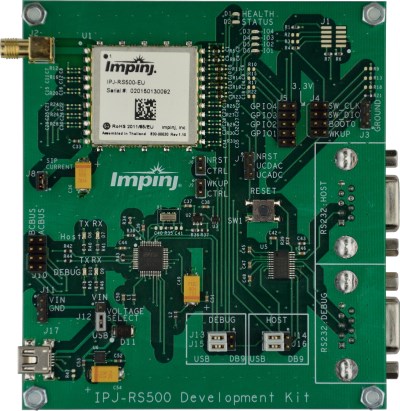
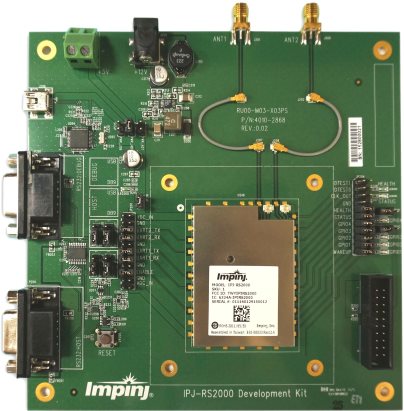
The Indy reader module Development Kits are designed to assist in evaluation and development with Indy reader modules. There are development kits for each of the Indy Modules. If you have just received an Indy Module Development Kit, and would like to learn how to use it, please see the Quick Start Guide for the kit, which is included in the Release package under .\Documentation\ , or on the web here (for RS500) and here (for RS2000) .
Step 2. Examine the IRI and IRI-LT PC Host Examples
The next step in developing Indy Module host firmware or software is to take a look at the host PC examples that are shipped along with the ITK Release. These are stored within the Indy ITK Release package at .\ITK_C\Examples\ and .\ITK_LT_C\Examples\ . These examples demonstrate a number of functions of the IRI and IRI-LT libraries, and can be run on a host computer connected to an Indy Module Development Kit via USB. The examples are documented in more detail here: IRI Examples
Step 3. Develop IRI or IRI-LT Based Embedded Firmware
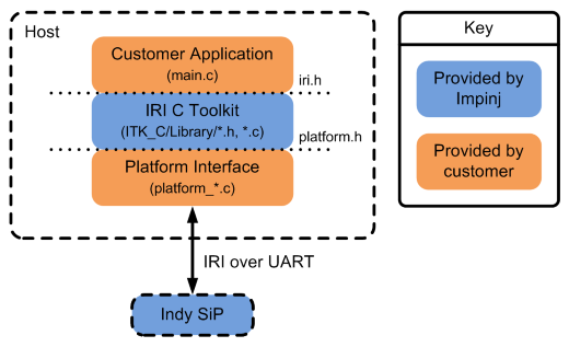
To develop your own embedded host firmware speaking IRI, you’ll need to integrate the IRI or IRI-LT libraries into your embedded firmware project. The diagram below shows the source files required to implement an Indy Module based system. To implement such a system, create your own C or C++ project, and include iri.h or iri_lt.h, which are stored in the Release package in .\ITK_C\Library\ and .\ITK_LT_C\Library\ . You may also need to include ipj_util.h, if you want to take advantage of the API built into the ipj_util.c source code in that library, which is useful for development and debugging.
Before the included libraries will work, some platform specific code may need to be written. This code implements communication to and from the Indy Module over UART, and also some other functionality like event timing. This code is contained within the platform_*.c source files, which are stored in the Indy ITK Release package in .\ITK_C\Library\ and .\ITK_LT_C\Library\ . Source files platform_linux.c and platform_win32.c are provided to aid development. An empty platform library file, platform_empty.c is provided as a template. The text file PORTING.txt provides further details on porting device specific code. For more details on platform port examples, see the platform port example code listing.
Step 4. Develop Embedded Host Firmware using an Indy Module Development Board
The Indy Module Development Boards can be used as platforms for early development along with a third party development board. The board has connectors to facilitate easy connection of host UART pins and GPIOs to the pins of the Indy Module. For more details on how to use the Indy Module Development Boards in this fashion, see each Indy Module’s Hardware User’s Guide, which are included in the Release package under .\Documentation\ , or on the web here (for RS500) and here (for RS2000).
Step 5. Integrate an Indy Module Into a Custom PCB
For help designing a PCB to connect the Indy Module to a host, see the Indy Module Hardware User’s Guide, which is included in the Release package under .\Documentation\ , or on the web here (for RS500) and here (for RS2000).
Step 6. Review Additional Information
For more information, see the following documentation:
- View the rest of the Release documentation such as the overview.
- View the rest of the Indy Module Hardware documentation, such as the Datasheet and Hardware User’s Guide, which are included in the Release package under .\Documentation\ , or on the web here.
- Browse through the Frequently Asked Questions.
- Visit support.impinj.com, where you can submit support tickets and engage in technical discussion.
![]()
Table Of Contents
- Quick Start Guide
- Introduction
- Step 1. Get Started with the Indy reader module Development Kits
- Step 2. Examine the IRI and IRI-LT PC Host Examples
- Step 3. Develop IRI or IRI-LT Based Embedded Firmware
- Step 4. Develop Embedded Host Firmware using an Indy Module Development Board
- Step 5. Integrate an Indy Module Into a Custom PCB
- Step 6. Review Additional Information